User Tools
Table of Contents
Water Cooler Conversion
By Ron Bean May 2013
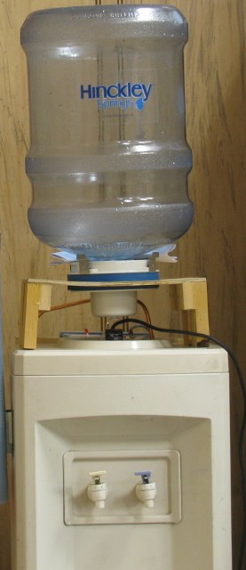
In addition to the obligatory refrigerator full of soda (or sometimes empty of soda, depending on whether anyone's filled it recently), we also have a water cooler that takes the big 5gal water bottles. They also sell coolers that can be plumbed into a water line, and a while back I discovered that they're actually bottle-type coolers that come with a conversion kit. The kit consists of a float switch and a solenoid valve, and a mounting bracket that takes the place of the bottle holder.
There isn't a conversion kit for the cooler we have, but it looked simple enough, so I made one from scratch. I don't like float switches, so I used two other methods of sensing the water level (I wanted a backup sensor because certain failure modes could result in an unlimited amount of water on the floor, which would be a Bad Thing). Instead of trying to find the “best” way to do it, I used the components I was interested in learning about.
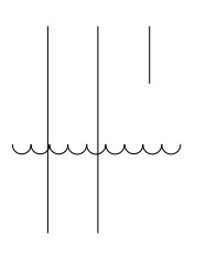
We had a bunch of surplus capacitive proximity sensors, which would have been an obvious choice, but for a while I couldn't find the box they were in. Later someone told me where they were, so that became the backup sensor. In the mean time, I looked at sensing the conductivity between two stainless steel probes in the water tank (which is one of several methods commonly used in industry). At the bottom of each probe are two stainless steel nuts tightened against each other, to give it more surface area.
This is the simplest possible circuit:
Note that tap water is not a very good conductor (in fact pure H2O, if you could find such a thing, would be a pretty good insulator). So when the water touches the probes, it forms a voltage divider with the pull-down resistor. To get a useful voltage, the resistor has to be fairly large– anything over 500K would probably work, I used 13M because it's the largest value we had on hand. A pull-up would not work, because the water probes could never pull the voltage down far enough to turn off the transistor (I used a 2N2222a, because we had a big bag of them). BTW the relay only sees 5V because of the voltage drop across the transistor (I think that's because it's not getting enough current to turn on completely). It would also be possible to use an op-amp for this, but I was more interested in learning about transistors.
So, what about using a power transistor instead of the relay? It would be nice if you could do this:
But that didn't work, because the transistor couldn't pull the voltage down far enough to turn off the power transistor (I've drawn it as a bipolar transistor for simplicity, in practice it would be a Darlington or a power MOSFET– they both work, but you get more geek points for using a MOSFET). It might have worked if I'd used a MOSFET (or an op-amp) in place of the 2N2222a, but instead I got interested in driving the power MOSFET from logic gates (more on this below):
In this case I just needed an inverter– I'm using one gate from a 4001 quad NOR gate, because I had one handy (remember to ground all unused inputs– letting them float could cause the chip to draw too much current and overheat). The resistor between the inverter and the MOSFET is a precaution I've seen mentioned when using logic gates to trigger a MOSFET driving an inductive load, I'm not sure what it actually does (there's no voltage drop across it, because MOSFETs have no input current, but it must do something during transients).
This is the actual board:
Most of the wires are distributing power to various parts of the board. On the left is the 9V regulator, to the right of that is the 4001 quad NOR gate, then the two transistors, and the relay used by the proximity sensor. The heat sink on the MOSFET isn't really necessary, because it's only on for a few seconds at a time. But during testing I accidentally left it on long enough for it to get too hot to touch (and it started to melt my breadboard). Since I had a clip-on heat sink that was the right size, I decided to use it.
Here's the top of the box– if the backup sensor triggers, it lights an LED to let me know that something went wrong so I can fix it (this is in a carpeted area, so I really don't want to get water on the floor).
This is the tap from the water supply. The needle valve is opened just far enough to let the water flow, but not so far that it can keep up with the faucet draining the tank– that keeps it from flipping on and off while you're drawing water from it.
More on sensing water levels
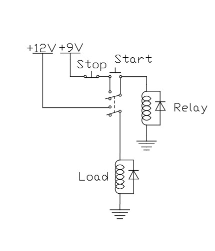
In most cases you'd have separate sensors for high level and low level. Note that the high level is inherently “active high” (that is, normally open), while the low level is inherently “active low” (normally closed). With relays, the circuit would look something like this:
Which sensor is which depends on whether you're trying to fill the tank or empty it (and if you're trying to fill it, you'd have to invert the signals). This can also be done with logic gates instead of relays (which is why I was playing around with them above), but I'll leave that as an exercise for the reader.
Notes on solenoid valves:
There are any number of solenoid valves available. If you're using an AC solenoid, you'd use a solid-state relay in place of the power MOSFET.
I played with these two from Adafruit:
http://www.adafruit.com/products/996
http://www.adafruit.com/products/997
The plastic valve has straight threads (not tapered pipe threads), and I've only found two fittings that work with them. One is the hoses that are used for things like toilet supply lines– they use a gasket for sealing, so they can have straight threads. But they only engage a few threads, and the plastic threads on the valve are easily damaged. The other fitting is called a “CTS” adapter, which is a quick-connect fitting that's normally used with PEX tubing, but will also work with CPVC or copper pipe. I found them locally, but here is one supplier:
http://www.dyersonline.com/seatech-1-2-cts-x-1-2-nps-female-swivel-connector.html
They're sometimes labeled “FIP” (for Female Iron Pipe), but they're actually straight threads, and they engage more securely than the other type. Sparkfun also sells a version of this valve with 3/4“ threads.
The brass valve is the one I'm actually using now, and despite what their description says, it does matter which way you connect it– I discovered that if you hook it up “backwards”, city water pressure is enough to push the valve open! If you look at the side of the valve, the sloped part is towards the inlet. My fittings still leak slightly, and eventually I'll fix that, but for now I have a bucket under it.
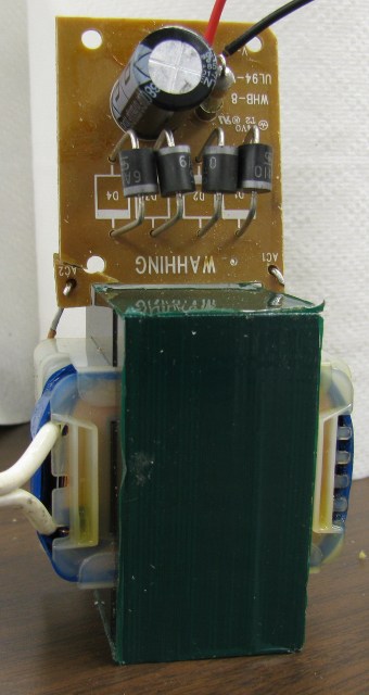
This valve draws 3 amps at 12V, which requires a large power supply. This is the one I'm using– it doesn't get any simpler than this! Open circuit voltage is about 15V, which draws down to 12V when the solenoid is turned on. I used a 9V regulator for the other components so the voltage wouldn't fluctuate. (If you look closely, you might notice that one corner of the circuit board was broken off in shipping– I sanded off the solder mask and soldered a piece of 12 gauge wire across the back).
Additional notes
- I noticed some scale in the reservoir so I cleaned the cooler on 5/21/15
- I wiped down the inside then added 1 tablespoon of bleach to a quart of water, ran that through, then I flushed a little over 10 gallons of water through the tank, alternating between the two spigots.
- I managed to overheat the solenoid valve and it failed closed. I unplugged the controls, waited about 10 minutes and the valve reset itself after cooling down.
- I'm going to check with Ron about the metal leads, there's some galvanic action. The machine screw connected to the red wire appears to be turning a reddish yellow color.
- 2017-02-07 It looks like the valve likes to fail open if it has been activated continuously for a few days (like when the water is turned off at the valve, but the cooler is not turned off.) Cleaned the valve, strengthened the spring holding it closed, put up an explanatory sign and added a loud buzzer to the overflow sensor to hopefully annoy someone enough to shut it off if it's overflowing.
- If you hear the alarm, immediately shut off the T-valve behind the sink and drain the cooler until the alarm shuts off. If the water has to be shut off to the cooler for any reason, turn off the switch on the cooler so the valve doesn't sit in the open position for a long period of time and get stuck.


