User Tools
This is an old revision of the document!
Table of Contents
Rat Rig V Core 3 Core XY 3D Printer
A Milwaukee Makerspace Project by John Klein
Introduction
The Rat Rig V Core 3 is an open source premium Core XY 3D printer. The goal of this build is to make a high speed, high quality, large format 3D printer that is easy to use and reliable.
What is a Core XY 3D printer? I would highly recommend a quick read of this article by All 3DP to give you more detail but in short, the X and Y stepper motors work together through a long belt to move the print head. This reduces the amount of mass that needs to be moved which results in much less vibration, reducing print artifacts and allowing for higher print speeds at the cost of additional complexity during construction.
Another benefit of this particular design is the kinematic print bed. This is mounted on three, individually controlled steppers to allow full control over the bed position and angle. An immediate benefit of this system is fully automatic bed leveling but I hope to utilize this system for non-planar 3D printing in the future.
This printer can also be fully enclosed at a later date to allow for the printing of more temperature-sensitive filaments like ABS.
Build Log
Mechanical
04/22/2022
Main shipment of materials received
Configuration:
- Build volume 400mmx400mmx400mm
- Controller: BTT Octopus v1.1, 6xTMC2209 stepper drivers, Raspberry Pi 3B
- Hotend: Slice Engineering Mosquito Magnum, 60W heater
- Extruder: Bondtech LGX Lite
- Steppers: 5x Nema 17
- Bed heater: Keenovo 1000W/120V heater pad
- Power Supply: Weho 250W fanless
- Bed Leveling: Antclabs BLTouch v3.1
04/23/2022
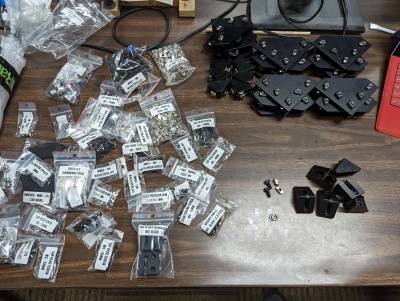
Began work on assembling the frame. This is made mostly of 30mm v-slot aluminum extrusion. All of the necessary pieces were sorted and labeled.
Prepared the frame brackets. This was the most tedious part with 4 lower and 16 side, and 10 corner brackets to insert nuts and bolts into.
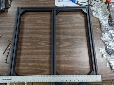
Assembled the electronics frame, ruler shown for scale
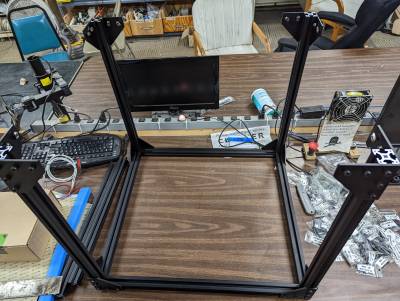
Assembled most of the printer frame.
And here is the sum total of about 2.5 hours of work. Making sure everything is square was very important at this phase of the build.
The next step is to get the electronics panel cut from acrylic before finishing the frame and beginning on the motion system.
04/24/2022 - 05/01/2022
Laser cut the electronics panel from 1/4“ clear acrylic. Attached to the electronics inner frame and attached that to the outer frame. Getting the frame fully square was difficult and required a fair amount of loosening and adjusting the assembly to get everything together correctly.
Assembled the left and right X/Y stepper mounts and routed the belts.
Assembled and attached the front belt idlers and routed the belts.
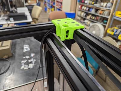
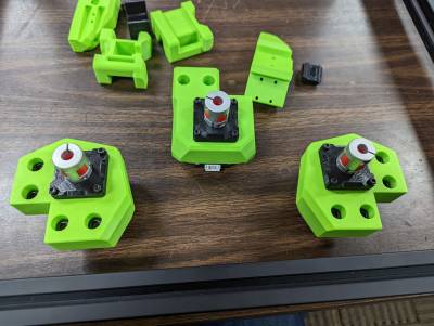
Assembled the 3 Z-axis motor mounts. This design uses thrust bearings between the motor mount and the clamp to prevent the stepper from carrying any vertical load.
Attached the Z-axis mounts to the frame. They will need some adjusting to line up the z screws with the linear rails so they are intentionally left slightly loose.
The next step is attaching the linear rails and assembling/mounting the X gantry. It's starting to actually look like a 3D printer now!
05/02/2022 - 05/06/2022
Prepared the linear rails. These are held in with M3 bolts and T-nuts that slot directly into the aluminum extrusion.
Mounted the linear rails. It was very important to keep the rails square with the frame. Any deviation here can result in print defects.
Prepared and mounted the X gantry. This is the only part that uses 20mm aluminum extrusion.
Prepared the bed arms and mounted them to the rails.
Prepared and mounted the bed. This uses a very clever design that allows for only outward movement from thermal expansion to prevent bed warping.
Began work on the EVA carriage. This is a modular design that allows for several different hotends and extruders so if I wanted to change to a different component in the future I could.
Once the hotend components are complete it will be time for electronics and firmware!
05/07/2022
Here's probably the most expensive part of the build by weight: the hotend. This is a Slice Engineering Mosquito Magnum. Also included were a couple orange flavored suckers.
I had to open up the extruder to add in some square nuts for mounting. This also gave a great opportunity to see how the extruder gears and tensioner are arranged.
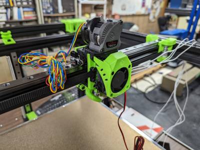
Mounted the hotend and extruder with a small piece of PTFE tube between them to guide the filament.
Then the cooling fan and shroud. This part is really begging for some googly eyes.
Added the part cooling fan and cable management bracket.
And that's it! The printer is mechanically complete!
Now it's time for the electronics, wiring, and firmware. Then it's time for the first calibration prints!
Electrical
Well, here it is; the super tedious part. Pictures of work in the mechanical section each represented about 30 minutes of work. Each of the following pictures represents about 1-2 hours of work.
Mounted up the electronics to the acrylic panel. On the left is the power supply and the solid-state relay, and on the right is the Raspberry Pi and BTT Octopus mainboard.
Shortened stepper wires and crimped JST connectors. The stepper wires included in the kit were too long and they were terminated with the wrong connectors. While they would have worked, the connectors would have been easily removed by mistake and the wires would have been a mess.
Firmware
Coming soon!
Calibration
Coming soon!

