User Tools
This is an old revision of the document!
MegaMax 3D Printer
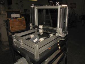
Plastic extrusion type 3D printer with approximately 1 cuft build envelope. My goal is to print life-sized human skulls from CT scan data. The machine uses 80/20 type aluminum extrusions for the frame and many scrounged parts generously supplied by the hack-rack, Tom G., and others at the makerspace. The design is loosely based on the MendelMax (Y-axis base, extruder on X-axis boom lifted by Z-axis screws), but I am sort of designing/cobbling as I go, one axis at a time, and fabricating parts as needed to fit the other pieces I have in-hand.
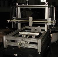
As of June 10th, this is what it looks like:
All three axes are nearly complete- just need to make the print platform for the Y-axis, and the print head(s)/extruder for the Z-axis. The X-axis is missing an idler pulley that will be added later this week. I have ordered a suitable belt and drive pulley for the Z-axis. With a little luck I'll be able to run some motion tests on the machine this weekend and see if my “precision” building practices have resulted in orthogonality of the axes and parallelism of the guide rails in each axis.
I have ordered a dual printhead from a KickStarter project that won't ship until August, so I'll start looking for another print head to use in the meantime.
Update: June 15th
I have fabricated the pulley for the far end of the X-axis, and the belt and drive pulley for the Z-axis screws arrived today. Looking forward to some simple motion tests this weekend. Working on the print platform design tonight…
Update June 17th:
The alignment technique for the X-axis guide rails worked as planned- I screwed an aluminum plate to the bushing blocks at the non-adjustable end of the guide rails then slid the assembly to the other end and tightened the screws that hold the guide rails. Next I cut and mounted the belt and it seems like I get very smooth motion all the way across the X-axis.
I also put the belt and drive pulley on the Z-axis and found that it too moves through the full range of motion without binding and no adjustment was necessary.
I made a plate to mount on the Y-axis bushing blocks and found that the end pieces that hold the guide rails do not allow for easy adjustment of their positions. I'm going to redesign and fabricate the Y-axis guide rail end plates, possibly today.
Update June 19th:
I made a test plate for the Y axis, made a new mount for the Y-axis guide rails, installed a belt on the Y-axis, widened the slots for the belt on the X-axis.
Problems:
1) the motor and far-end pulley mounts for the Y-axis don't allow for easy adjustment of belt tension. Redesign coming up!
2) aligning the Y axis guide rails parallel to each other is proving to be a problem. When I widened the belt slots on the X-axis guide rail mounts, I had to take the entire X-axis assembly apart. It went back together and the guide rails lined up with each other very easily. The Y-axis rail alignment was another story. I tried the same technique of screwing the bushing blocks to the plate at one end, then sliding it to the other end of the rails and tightening the bolts. The result was difficult sliding. I think the problem is that there is no “reference” rail to which both Y-axis guide rail mounts are bolted. The relative positions of the two mounts is at the mercy of how the frame of the machine is bolted together. Redesign coming up!
Update 8/12/12 Above listed problems have been fixed. Electronics ordered, delivered, connected and tested. Problem: Marlin firmware flashed on controller board not really suitable for my printer. Solution: download Marlin, modify config.h and pins.h files, compile, and update firmware on controller board. New problem: Marlin will not compile with latest Arduino IDE. Solution: spend a week chasing problems and get nowhere. Real solution: go to 3D printing meet-up at Bucketworks, hope someone has mercy on me and can help get it working. As luck would have it, Gary Kramlich was present and has much better kung-fu than I. In 5 minutes he had located the issue, fixed it, and I was able to update the firmware. It turns out the IDE had a macro that defined a mathematical “round” function which was in conflict with the round function in the math library of the C compiler. Commenting out the macro in the IDE allowed it to compile the firmware.
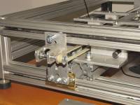
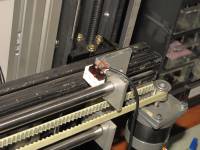
Photos show how I made a belt tensioner for the Y axis (a direct rip-off of the design used for the rep-rap Mendel), and how I have used Lego bricks to mount my end stop switches. I also cut the bushings for the Y axis in half to reduce drag and ease alignment, and added a “spine” to the Y axis similar to the 8020 spine of the x-axis.
Once I have the extruder mounted I'll have to calibrate everything and that will mean updating the firmware again, but that's a pretty easy process now.


